 |
| A picture from a future part of the restoration since this post is a little shy on visuals. |
Last week we took a look at the power supplies that are housed underneath the desk in the eurocard bay. We will now take a look at a couple of the other modules under there. I originally planned to cover all of them today but I got a bit carried away and decided to split this section into two parts.
There are five different cards. Let's start with the relay modules:
1) 1.915.603.00 - 9 Relay Sign. A (x2)
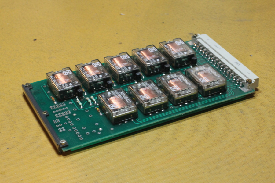 |
| 1.915.603.00 - 9 Relay Sign. A |
Studer 900 Series - Remote Control Signalization for Reproduction Equipment
Studer 900 Series - Remote Control Signalization for Reproduction Equipment Flow Chart
Simply speaking, this unit is used to allow each channel to individually control other pieces of equipment. Specifically, the logic in the console requires a certain set of parameters to be met before it will send a signal to external machines (see the bottom of the PDF linked above). As long as these conditions are met, a set of relay contacts can be opened or closed based on whether the fader on a certain channel is at the bottom position (OFF) or any other position (ON).
I'm not exactly sure of the application for this in broadcasting, but I assume that you would want to do something like start playing a tape when you push a fader up. This would be possible with this system.
I find this feature quite intelligent:
Imagine that you have two different tape machines that you would like to control, but will never use at the same time. You place the output of the first tape machine on the Line Input of Channel 1 and the output of the second tape machine on the Tape Input of Channel 1. Ideally, you would like to only control Tape Machine #1 when Channel 1 on the console is set to Line and only control Tape Machine #2 when Channel 1 on the console is set to Tape.
Studer has built this feature into the console. Allowing for two separate control lines, you may close two separate sets of relay contacts based on whether you are in the Line or Tape position on one channel.
But wait! There's a catch. There are only two of these cards with 9 relays each.
RANDOM NOTE: 9 relays - 2 have both Normally Open [NO] and Normally Closed [NC] contacts available while the other 7 only bring out the NO contacts.
For the schematic, see Pg. 504 in the Studer Manual (ftp://ftp.studer.ch/Public/Products/Mixing_Analog/900/Manuals/900_Op_Serv.pdf).
This allows for a maximum of ONLY 18 sets of contacts to be controlled in the console. So how have they configured it? There are 24 channels, each with 2 separate possible control lines. Are the first 9 channels exclusively hooked up? What if you want to customize it? Will you have to dig around inside of the console?
 |
| The two DB50 connectors that are labelled 'Fader' are the connections that one would hook jumpers up to. This would customize which channels would control which relay coils. The DB-50 connector labelled 'Relays' is where the relay contacts for the 18 relays can be found (which is how external equipment can be controlled). |
So cool! Now I just need to think of a reason why I would want to do this... hmmm...
2) 1.915.601.00 - 5/1 A Monitor Switch (x2)
Confession #2 - I didn't know what this module did before this blog either. You can't blame me though! I knew that they were relays for monitoring/signalling but, since they didn't need any repair/restoration, I hadn't got around to figuring out exactly what each one did specifically. Well I have figured it out now!
 |
| 1.915.601.00 - 5/1A Monitor Switch |
For the schematic, see Pg. 500 in the Studer Manual (ftp://ftp.studer.ch/Public/Products/Mixing_Analog/900/Manuals/900_Op_Serv.pdf).
There are 15 different monitor sources available on this console which are all switched by relays. Here is a list of which ones are controlled by this card:
∑Mono
Group 3-4
Group 5-6
Group 7-8
External 2
External 3
External 4
Aux 1
Aux 2
Aux 310 total! Every relay on the two cards is utilized. This leaves 5 of the 15 switches unaccounted for. 4 of them are switched with...
3) 1.915.602.00 - 4/2 A Monitor Switch (x1)
 |
| 1.915.602.00 - 4/2 A Monitor Switch |
For the schematic, see Pg. 502 in the Studer Manual (ftp://ftp.studer.ch/Public/Products/Mixing_Analog/900/Manuals/900_Op_Serv.pdf).
Let's see which outputs go through this card:
Group 1-2
External 1
Aux 4
PFL/Solo (Unbalanced)Now you may be asking yourself...
'Ian, why are these signals on a 4/2 card instead of a 5/1 card?'.
'Good Question! By the way, I like your new haircut', I would answer.
Then we would go to Burrito Boyz.
Oops, I got off topic. I must be hungry. ANYWAY, the reason for this can be found in my manual (not online):
The switchboard 1.915.602.00 is part of the monitoring system. Three balanced and one unbalanced stereo source can be switched to the monitor inputs of the studio and also to the control room.
Aha! Did I forget to mention that there are TWO monitor outputs on the console? Well that clears that up! Now, I can only assume that the Control Room output would be the ones for the engineer and the Studio output would be for a separate room with musicians/actors/reporters/anyone else who may need to hear what is being broadcasted/recorded. I will discuss how this source is selected by the engineer in the future when I get to the monitor section itself.
You may have noticed that we've only covered 14 of the 15 monitor outputs! I will leave that and the last two cards for Thursday.
So you have made it to the end of the blog posting! Congrats! As I promised, here is the big news. Over the past ~6 months, I have been looking for a new studio space to house all of this useless junk that I have been working on. A couple of months ago, I finally found a great space. It's a 100 year old coach house in downtown Toronto. I am finally moving in on Sunday and I have already assigned my sister to taking complete documentation for us via my camera. I think it'll be a bit of a time crunch, but I plan on posting a blog of the entire move next Monday if I have enough time to unpack some things. Either way, There will always be something new to read Mondays and Thursdays at 10AM!
Thanks for reading!
Congrats on the studio space find, Ian! Enjoying your posts and looking forward to more. Might have some basic tech questions for you as well if you're willing to take the time :)
ReplyDeleteThank you very much Steve! It's great to hear that someone is enjoying the blog! I will definitely keep posting. Feel free to shoot me an email (I'll see if I can set it up on the website somehow) and I'll try to help if I can!
ReplyDeleteThanks again!